Volume 10 issue 6
What’s Happening at Missouri S&T:
(formerly UMR)
Short Course Dates
We will be offering "Introduction to Paint Formulation" October 21-25, 2013 (Fall 2013) . This course is intended to give the person a fundamental knowledge of how to approach a starting formulation and troubleshoot it. This course involves both lecture and laboratory work.
For more information see our web site at http://coatings.mst.edu and to register contact Catherine Hancock at cemv26@mst.edu or coatings@mst.edu or call 573-341-4419. **These courses are held on the Rolla Campus**
Online Short Course
We are offering "Introduction to the Coating Systems" online short course. This course is targeted for automotive and aviation type OEM companies. This self-paced seminar will cover the painting system from the composition of paints to the evaluation of the dry film. The pigments, resin, solvents and additives will be discussed including their influence on the coatings performance. Color measurement, surface profile, and other evaluation criteria will be related to composition. The importance of surface preparation and other manufacturing criteria will show the system complexity and each step's importance.
We are offering "Surface Defects: Elimination from Human and Process Contaminants" online short course. This course addresses many of the issues in prevention and minimization of defects. The course covers the defects caused by the coatings process, as well as human issues, including personal care product causes. Several of the surface defects are discussed – from basic principles and real world automotive and aircraft examples. The highly practical approach of this course will greatly aid the personnel involved in the painting operation to reduce and systematically approach issues.
Employment Tab
We have started an employment section for our students and companies. We have a full time job section, an intern / co-op section and a graduating and alumni students section . Please explore our section on employment on our web site. Anyone wanting to have job opening listed, please contact us at (573) 341-4419 or e-mail: svgwcc@mst.edu . You can also write to us at Missouri S&T Coatings Institute, BOM #2, 651 W. 13th St., Rolla, MO 65409-1020. Our web site is http://coatings.mst.edu
Technical Insights on coatings Science
Electrochemical Impedance Spectroscopy (EIS)
As a powerful tool in coating evaluation
Yousef Dawib, Graduate Research Student, Missouri S&T
Electrochemical impedance spectroscopy (EIS) can be considered one of the most promising techniques in characterizing coating integrity. As a result of the high resistivity of organic coating the traditional DC techniques can not be used (1). Therefore, the need for an alternative method has emerged. With the use of EIS, it is possible to determine many parameters such as coating capacitance, coating resistance, and corrosion process occurring at the metal-coating interface (2).
Basis of EIS:
The EIS technique involves measurement of alternating current AC impedance over a range of applied frequency. Potential applied over frequency range between 0.01Hz to 100 kHz. The reason for using this broad range is to detect both fast and slow reactions, the higher frequency for fast reaction and the low frequency for slow reactions(3). The Figure (1) illustrates the applied perturbation and responded current.
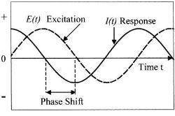
Figure (1):- Schematic potential excitation and responded current (4)
By looking to the figure (1) we can easily see there are two parameters characterizing this response, the ratio of voltage to current and phase shift. The combination of two parameters will give the impedance ¿ z ¿. This impedance contains elements of an equivalent circuit, such as capacitors and inductors. Not to go deep in mathematical derivation and just simply show what the impedance means.
First the excitation voltage expressed as a function of time:
Et = E0 sin (ω t)
Et is potential at time t, Eo is amplitude of signal, and ω is radial frequency.
Second the response current is shifted in phase and can be expressed by
It = Io sin (ωt + ¿)
It is the response signal at time t, Io is the maximum amplitude, t is the time, ω is radial frequency, and ¿ is the phase shift.
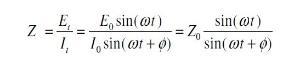
In view of Ohms law, the resistance R is equal to the voltage divided by the current. In analogy to this the impedance is:
Electrical equivalent circuits:
There are two common electrical circuits that represent coated substrate in EIS experiments:
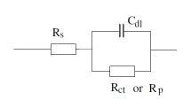
1. Randle cell:
Simple cell consist of solution resistance, coating capacitance and coating resistance. This cell represents intact coating and no sign of coating degradation:
2. Equivalent circuit for damaged coating:
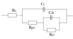
Where Rs or R¿: Solution resistance, Cc: Capacitance of coating, Rpo: Coating Resistance, Rct: Charge transfer resistance of metal substrate and Cdl: Double layer capacitance of polymer/ metal interface
All these parameters can be quantitatively measure by means of electrochemical impedance spectroscopy. Each parameter is associated with a property of the coating film.
Coating Capacitance:
One of the most important paramete of coating that can be measured by EIS is capacitance. The coating capacitance will change during the environmental exposure of coated substrate. The coating capacitance can be affected by different chemical and physical properties(3) :
Cc = (¿) (¿o) (A) / d
Where Cc is coating capacitance, ¿ the dielectric constant of the coating, ¿o is the dielectric constant of free space (8.854x10⁻¹² F/m), A is coating exposure area, and d is coating film thickness. The relation between capacitance to the magnitude of the impedance (|Z|) can be expressed by:
|Z| = 1 / (2pf Cc)
Where f is the frequency of the applied AC voltage.
Coating Resistance:
The exposure of coating to humid environment causes the coating resistance to decrease. This resistance referred as pore resistance Rpo (3).
Polarization Resistance (Rp):-
The polarization resistance is a parameter that describes the corrosion rate of metal substrates. Using EIS will provide information about the corrosion that take place under the coating at metal-coating interface (3).
Presenting EIS Data:
The collected data can be presented via two plots: Nyquest plot and Bode plot
Nyquist Plot:
The impedance is composed of a real and an imaginary part. In a Nyquist plot the real impedance is plotted on the X axis and imaginary impedance on Y-axis. The plot in Figure 2 represents the expected response of a simple circuit. The resulting semi-circle will appear on the plot. At the leftmost end of the semicircle, the frequency reaches its high range. And the frequency reaches its low range at the rightmost end of the semicircle. By extrapolating semicircle toward the left, down to the X-axis we can easily read the solution resistance (5). Polarization resistance can also be read from semicircle extrapolation by extrapolation semicircle toward the right. Also from this plot we can use the frequency corresponding to the top of semicircle, ωmax to calculate coating capacitance.
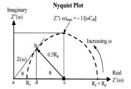
Figure (2): Ideal Nyquest plot of impedance (4)
Bode Plot:
The impedance plotted with log frequency on X-axis and both absolute value of impedance and phase shift on y-axis. Figure 3 shows a Bode plot .Since frequency appears on one of the axes; it is easy to track the effect of the frequency on the impedance. Plotting the logarithm of frequency allows the use of wide frequency range (5). Moreover, the Bode plot yields the values of polarization resistance and solution resistance. Solution resistance can be read from the high frequency horizontal plateau. On the other hand, the polarization resistance can be determined at low frequency. Finally, at intermediate frequency, the curve represents a straight line with slop of -1. Extrapolation of this line to Y-axis yields the value of coating capacitance (5).
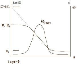
Figure (3):- Bode Plot (5)
References:-
- Mansfeld. F, and Kendig. M.W, “Electrochemical Impedance Tests for Protective Coatings’’. ASTM STP 866, 1985. PP 122-142
- Ursula Rammelt and G. Reinhard, Progress in Organic Coatings, 21 (1992) 205-226.
- David Loveday, Pete Peterson, and Bob Rodgers,Part 2: Application of EIS to Coatings. Gamry Instruments, Oct 2004
- Electrochemistry and Corrosion Science, Nestor Pereze, Kluwer Academic Publishers, 2004.
- Application Note AC- 1, Basics of Electrochemical Impedance Spectroscopy Princeton Applied Research.